Tele® Harness Install

Install help and guides for your ObsidianWire Tele® harness
Guitar Electronics by ObsidianWire - Page Banner
  • Easy. Not Instant.

    For a secure connection, take your time, and follow directions carefully.

Layout Guide for Installing ObsidianWire for Telecaster harness.

Will It Fit?

Layout Guide: For Telecaster

Fits genuine Fender Tele

Will not fit Squier or 'Metric' sized plates and knobs.

Always Check Hole Layout

  • Hole Size: 9.52mm (3/8”)
  • Control Hole Spacing: 63mm (2.48")
  • Knob Size:  Solid Shaft 6.35mm (1/4") US SPEC
  • Switch Tip: CRL/OAK type 1.32mm x 4.78mm (.052" x .188")

DOWNLOAD GUIDE

Wiring Diagrams

Match your wiring diagram to your Pro-Wired Electronics model. Check carefully.

Notes:

  • Slot 1 - Always Closest to Jack
  • Ground all metal parts including tremolo / bridge and cavity sheilding

  • VINTAGE PLUS FOR TELE®

    Insert wires to slots as below

    1 = Spare Ground
    2 = Spare Ground
    3 = Spare Ground
    4 = Spare Ground
    5 = Output Jack Black
    6 = Output Jack White
    7 = Neck Ground
    8 = Neck Hot
    9 = Bridge Ground
    10 = Bridge Hot

  • CUSTOM UNIVERSAL FOR TELE®

    Insert wires to slots as below

    1 = Output Jack Black
    2 = Output Jack White
    3 = Neck Series
    4 = Neck Series
    5 = Neck Hot
    6 = Bridge Series
    7 = Bridge Series
    8 = Bridge Hot

    Notes:

    • Pickup Ground: to spare ground post
    • All Other Ground: to spare ground post
    • Two Wire Pickups: Leave 'Series' Slots empty
    • Braided Wire: See tips below
  • CUSTOM NASHVILLE '7-WAY' FOR TELE®

    Insert wires to slots as below

    1 = Output Jack Black
    2 = Output Jack White
    3 = Neck Ground
    4 = Neck Hot
    5 = Middle Ground
    6 = Middle Hot
    7 = Bridge Ground
    8 = Bridge Hot
    All other ground wires to screw down ground connector

  • CUSTOM 4-WAY FOR TELE®

    Insert wires to slots as below

    1 = Spare Ground
    2 = Spare Ground
    3 = Spare Ground
    4 = Neck Cover Ground (As Below)
    5 = Output Jack Black
    6 = Output Jack White
    7 = Neck Ground
    8 = Neck Hot
    9 = Bridge Ground
    10 = Bridge Hot

  • 4-Way Pickup Mod

    Required for: Metal covered neck pickups used with the Custom 4-Way for Tele®

    This mod is NOT required for three wire neck pickups.

    The mod adds a seperate ground wire for grounding the pickup cover.

    1. Identify and cut the link between the existing ground wire, and the pickup cover.
    2. Solder a new ground wire directly to the pickup cover.

    Demo Video

Custom Universal For Tele®

Braided Wire Tip

Vintage style braided wires can be used with the Custom Universal for Tele® harness.

Thread the entire wire through the ground post and lightly clamp down with the grounding screws

Send the inner core wire to the 'HOT' solt on the solderless connector

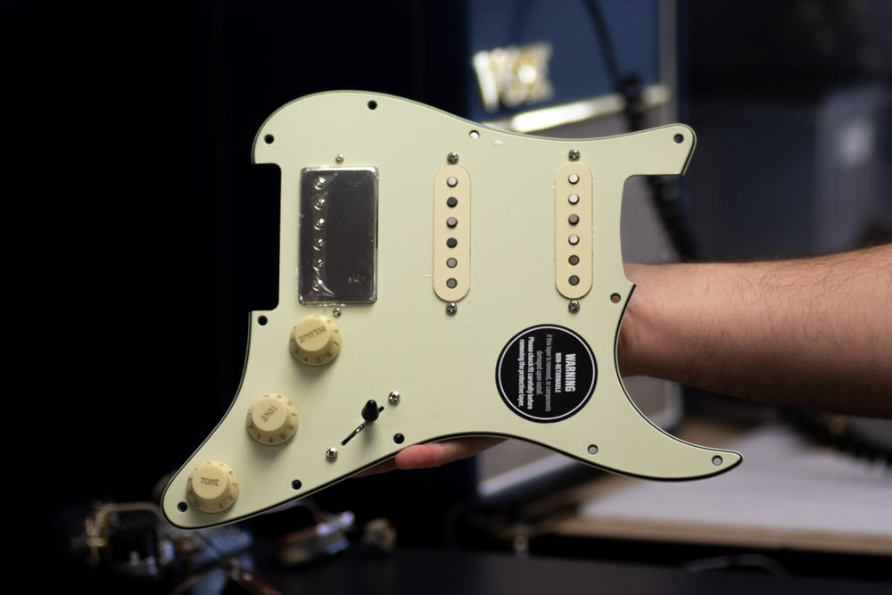
Installing your new Tele® Harness

  • 1) Find Your Diagram

    • Find the correct diagram for your Tele above.
    • Alternatively, you can download the full printable version for your Tele below.
    • DOWNLOAD MANUAL
  • 2) Identify Your Pickup Wires

    • For most pickups:
      Hot = White
      Ground = Black
    • For different pickups you can check your pickup builders manual
    • MORE PICKUP INFO
  • 3) Cut Out Your Old Harness

    • Cut the pickup, and ground wires from your old harness, and remove it from your bass.
    • Cut as close to the old harness as possible to maintain the length of your wires.

  • 4) Prepare Your Wires

    • Strip pickup and ground wire insulation leaving 6mm (1/4”) of bare wire.
    • Be Precise
    • Twist loose strands of wire between your fingers to create a firm tip.
  •  

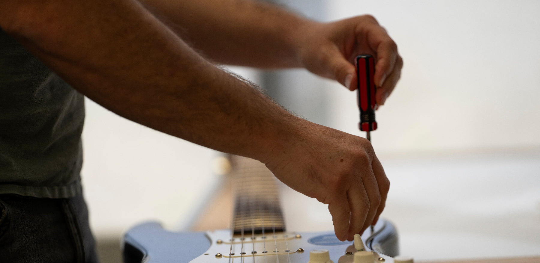
    5) Press & Hold Connector Button

    • Use a fine screw driver to press and hold the connector button above the wire slot.
    • For a full guide on using the solder-less connectors, check below
    • CONNECTOR GUIDE
  • 6) Insert Wire & Release Button

    • Insert the wire to the correct slot at a 45° angle.
    • Release the button and the wire should hold firmly.
    • Test the wire by giving it a gentle pull before moving on to the next wire.

Install Demo

More Help?