Tele® Harness Install

Install help and guides for your ObsidianWire Tele® harness
Guitar Electronics by ObsidianWire - Page Banner
  • Easy. Not Instant.

    For a secure connection, take your time, and follow directions carefully.

Install Info:

Below you will find:

  • Layout Guide
  • Wiring Diagrams
  • Install Instructions
  • Demo Videos
  • Links to More Help
Layout Guide for Installing ObsidianWire for Telecaster harness.

Will It Fit?

Layout Guide: For Telecaster

Fits genuine Fender Tele

Will not fit Squier or 'Metric' sized plates and knobs.

Always Check Hole Layout

  • Hole Size: 9.52mm (3/8”)
  • Control Hole Spacing: 63mm (2.48")
  • Cavity Depth: Minimum 34.5mm (1.3”) // (30mm depth required around push/pull pots)
  • Knob Size:  Solid Shaft 6.35mm (1/4") US SPEC
  • Switch Tip: CRL/OAK type 1.32mm x 4.78mm (.052" x .188")

DOWNLOAD GUIDE

Wiring Diagrams

Match your wiring diagram to your Pro-Wired Electronics model.

Check carefully.

Notes:

  • Slot 1 - Always Closest to Jack
  • Spare ground wires go to screw down connector
  • Ground all metal parts including tremolo / bridge and cavity sheilding

  • Vintage '3-Way' (T3 Vintage 250k)

    Insert wires to slots as below

    1 = Spare Ground
    2 = Spare Ground
    3 = Spare Ground
    4 = Spare Ground
    5 = Output Jack Black
    6 = Output Jack White
    7 = Neck Ground
    8 = Neck Hot
    9 = Bridge Ground
    10 = Bridge Hot

  • CUSTOM NASHVILLE '7-WAY' (T7 Custom)

    Insert wires to slots as below

    1 = Output Jack Black
    2 = Output Jack White
    3 = Neck Ground
    4 = Neck Hot
    5 = Middle Ground
    6 = Middle Hot
    7 = Bridge Ground
    8 = Bridge Hot

    All other ground wires to screw down ground connector

  • CUSTOM UNIVERSAL (T3 Universal)

    - Including Split Coil Version

    Insert wires to slots as below

    1 = Output Jack Black
    2 = Output Jack White
    3 = Neck Series 1 - Coil Tap
    4 = Neck Series 2 - Coil Tap
    5 = Neck Hot
    6 = Bridge Series - Coil Tap
    7 = Bridge Series - Coil Tap
    8 = Bridge Hot

    Notes:

    • Pickup Ground: to spare ground post
    • All Other Ground: to spare ground post
    • Two Wire Pickups: Leave 'Series' Slots empty
    • Braided Wire: See tips below
  • A close up image of the ObsidianWire custom universal wiring harness for Telecaster showing the method of install for vintage braided pickup wires

    Braided Wire Tip

    Vintage style braided wires can be used with the Custom Universal for Tele® harness.

    Method 1 - Shown

    Thread the entire wire through the ground post and lightly clamp down with the grounding screws

    Send the inner core wire to the 'HOT' slot on the solderless connector

    Method 2

    De-braid a section of the outer wire, ands end this to the screw down connector.

    Send the inner core, to the HOT slot of the solderless connector

  • CUSTOM 4-WAY (T4 Custom 250k)

    Insert wires to slots as below

    1 = Spare Ground
    2 = Spare Ground
    3 = Spare Ground
    4 = Neck Cover Ground (As Below)
    5 = Output Jack Black
    6 = Output Jack White
    7 = Neck Ground
    8 = Neck Hot
    9 = Bridge Ground
    10 = Bridge Hot

  •  

    Neck Pickup - 3 Wire Mod// Required for 4-Way Wiring

    Required for:

    • Two Wire Neck Pickup
    • With a Metal Cover

    NOT required for:

    • Neck Pickups that already have three wires
    • Pickups without a metal cover

    The mod adds a separate ground wire for grounding the pickup cover.

    1. Identify and cut the link between the existing ground wire, and the pickup cover.
    2. Solder a new ground wire directly to the pickup cover.

T4 Custom Install & Pickup Mod // Demo

Install Instructions:

  • Before We Start

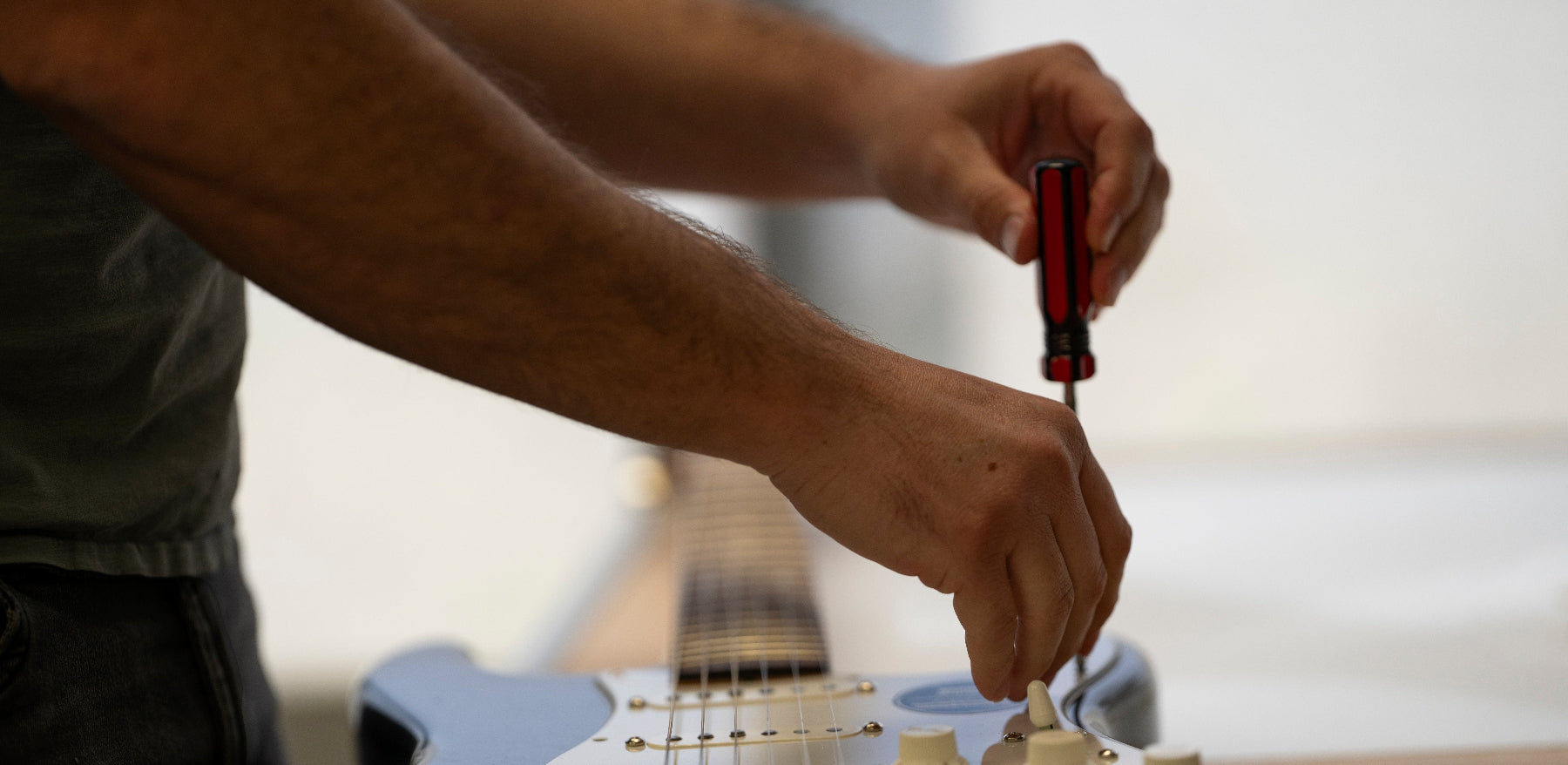
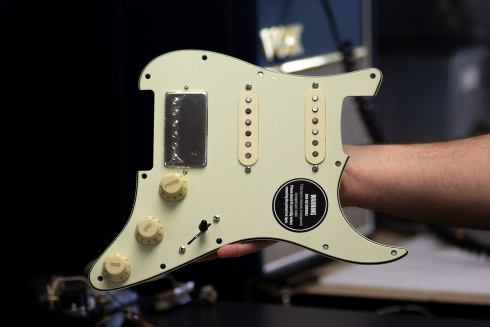
    Many of the following pictures show a Stratocaster install.

    We promise the process is the same for your Telecaster.

  • A man removing the pickguard from a black fender stratocaster.

    1) Prepare your space & set aside some time

    • A clean install is a good install
    • Take your time, and be precise
    • Wiring parts can be fragile. Be gentle.

    You will need

    • Wire cutters
    • Fine tip flat head screw driver
    • Phillips head screw driver for switch screws
    • Crescent or socket for potentiometer nuts
  • 2) Remove Your Old Wiring Harness

    • Cut the pickup, and ground wires from your old harness, and remove it from your bass.
    • Cut as close to the old harness as possible to maintain the length of your wires.
    • Remove the harness from your pickguard
  • 3) Mount your new Wiring harness to the Control Plate

    • Use the hardware provided to install your new harness
    • DO NOT remove the nuts that come pre-loaded on your harness. These act as a spacer between your harness and the pickguard

  •  

    4) Find Your Wiring Diagram

    • Find the correct diagram for your Tele® & Harness above.
    • Ensure the diagram is the correct one for the harness you are installing.
  •  

    5) Identify Your Pickup Wires

    • For most pickups:
      Hot = White
      Ground = Black
    • For different pickups you can check our pickup wire guide below, or check with the manufacturers install manual

    See Also

    Three Way Wire // Pickup Mod for the T4 Custom Install Above

    Pickup Color Codes
  • 6) Prepare Your Wires

    • Take your time & be precise
    • Strip pickup and ground wire insulation leaving 6mm (1/4”) of bare wire.
    • Twist loose strands of wire between your fingers to create a firm tip.
    • Cleanly prepared wires are essential for a good connection

  •  

    7) Press & Hold Connector Button

    • Use a fine screw driver to press and hold the connector button above the wire slot.
    • This opens an internal clamp so the wire can be inserted to the slot.
    • For a full guide on using the solder-less connectors, check below
    Connector Guide
  • 8) Insert Wire & Release Button

    • Insert the wire at a 45° angle.
    • Insert all of the exposed section of wire (6mm or 1/4")
    • Release the button and the wire should hold firmly.
    • Test the wire by giving it a gentle pull before moving on to the next wire.
    • Your solderless connector is made to fit a range of wire sizes, from standard Fender cloth wire down to tiny Seymour Duncan style wires
  • 9) Install knobs & Switch Tip

    • Use The correct size knobs & tips
    • Use Only US spec / 1/4" Knobs designed for Solid Shaft Pots
    • For Split Shaft Pots (e.g as used on T3 Universal & T7 Custom) use brass bushings provided before installing knobs
    • Screw down lug screw firm, but DO NOT over tighten
  • 10) Mount your control plate & String up for testing

    • Be careful to ensure that all wires are neatly tucked in to the cavity
    • Ensure that the switch and jack does not connect with the cavity wall as this can cause the signal to round out
    • Ensure that there is enough clearance at the bottom of the cavity, so the switch does not ground out on the cavity floor

Install Demo

More Help?